Fire Suppression Systems
Our HFC fire suppression systems are rated to protect areas against Class A, B and E fires and they function similarly to CO2 fire suppression systems. HFC fire suppression systems are usually used in enclosed areas where people are normally present, such as substations, server rooms, data centres, museums and hospitals.
We obtained various certifications for our Unique227 brand as follows:
UL Certification | FM Approvals Certification | SGP Certification
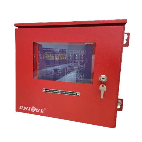
UNIQUE Fire Suppression Panel
TECHNICAL DATA Model FSP-02 AC Input Voltage 240VAC ± 10%, 50Hz DC Output Voltage 22 – 26VDC Standby Battery 24VDC Rechargeable SLA Type …
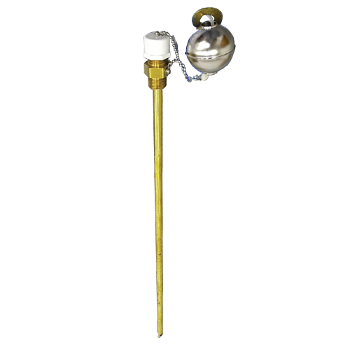
Liquid Level Indicator
Description
The liquid level indicator is a simple, manually operated device, which provides a means to determine the Clean Agent liquid level in vertically mounted agent storage containers. Once the liquid level is determined, it can then be converted into the weight of Clean Agent present in the agent storage container.
Operation
A magnet equipped float moves with the liquid level along the unit stem. Level readout is obtained by simply removing the protective cap and pulling out a calibrated tape until magnetic interlock with the float is felt. With the tape in this position, the reading is obtained at the point where the tape emerges from the unit housing.
When the liquid level is determined, the reading is then referred to a chart in the Engineering Manual and the corresponding weight of Clean Agent is determined. Accurate readings can be obtained over a +40°F to +90°F temperature range.
Features
- Reduced maintenance time – weight in an agent storage container can be determined in a fraction of the time it would take to remove and weigh them.
- Continuous fire protection – use of the liquid level indicator does not require taking out the cylinder from the system, thus providing uninterrupted fire protection.
- Field installation capability – the indicator can easily be installed in the field using a single wrench as long as the container is empty and is equipped with a mounting boss.
- Compact – when not in use, the unit requires no more space than that required by the container.
- Flexibility – the flexible tape design allows the unit to be used in tight spaces that would otherwise hinder the use of a rigid type indicator “stick”.
- Availability – units are available for all Unique containers from sizes of 150 lb to 1200 lb.
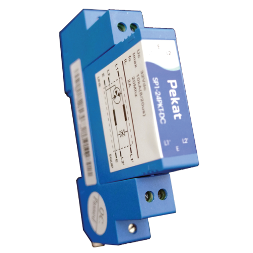
Signal Line Surge Protector
TECHNICAL DATA Model No. SP 1-24PKT-DC Part No. UFI227SP_S.LINE Standard Compliance 5kV (10/700 µs) to International Telecommunication Union (ITU-T K.20, K.21 and K.45) Maximum …
DEMCO Motorized Bell
A device that is designed to alert people that a fire may be present in the form of sound.
Latching Solenoid
Description
Latching Solenoid is utilized to open a Schrader valve on the top fitting connector of the cylinder valve. The application gives an answer to a quick reaction and a high latching power to be utilized with the UNIQUE Fire Extinguishing Liquid Agent. It was resolved that a latching solenoid with a discretionary nearby manual control head is the best answer for the application.
The actuator is held in the latching position without power until a flag from the operator discharge control board removes the permanent magnet. Whenever discharge, the latching solenoid opens the cylinder valve enabling the quenching medium to release from the cylinder into the system. The latching solenoid is designed with an emergency release local manual control to manually force the pin to depress the cylinder valve to release the extinguishing medium when needed. In order to reset the system, the solenoid is to be manually returned to the latched position. This custom latching solenoid designed specifically for fire protection systems is UL listed and tested in accordance with UL508.
Features
- High latching forces
- Fast response
- Options
- Manual release button cap
- Reset tool
- UL approval-recognized to UL864
- Tested in accordance with UL508
Specification
- Manual actuation force : 12-40lb ƒ (5.44 – 18kgƒ) max
- Operating force : 20.25 – 14.6lbƒ (90 – 65 N) min
- Power requirement : 24 VDC
- Current : 0.5A @ 24 VDC
- Electrical Connection : DIN 43 650-A / ISO 440 3 pin
- Operating Temperature Range : -4 to 131°F (-20 to 55°C)
- Weight : 1.9lbs (.86kg)
- Dimensions
- Body Diameter : 1.61 in (41 mm)
- Length : 4.17 or 5.9 in (106 or 150 mm) with manual actuation cap
Local Manual Control (Plunger Type)
The Local Manual Control Plunger Type features a local lever driven push rod that depresses a schrader check valve through the latching solenoid when fitted onto the top of the solenoid, thereby venting the pressure from the top of the piston in the cylinder valve, allowing the piston to slide upward and commence cylinder discharge.
- Use for manual actuation of cylinder
- Equipped with safety pull pin to prevent accidental discharge
- Solid brass construction
- Stainless steel operation lock-pin
Unique227 Clean Agent Cylinders 20-650lb
TECHNICAL DATA Part No. Cylinder Size Valve Size Dimension Max Fill Min Fill A B C UFI 90020-E* 20 lb 1” 10.750” 13.632” 18.633” …
Room Integrity Test
Enclosure Integrity Test
Now, the NFPA 2001, NFPA 12A, ISO 14520 and EN 15004 recognize an enclosure integrity test as part of the acceptance procedure for all clean agent systems. This includes halocarbon and inert agents. The comprehensive test and calculation procedure predicts how long the agent would stay in the room if it were ever discharged.
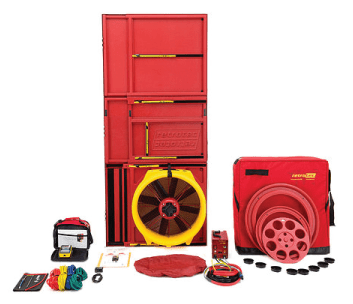
The Enclosure Integrity Test’s primary goal is to predict the enclosure’s retention time in the event that the Clean Agent Fire Suppression System is discharged. This is accomplished by performing a Door-Fan test.
What is a Door Fan Test?
Door Fan Test, also known as a Room Integrity Fan Test, is simply a way to measure the leakage of a protected room. A large fan is temporarily installed in the doorway of the protected room to be tested, with the fan blowing into the room (pressurizing the room). The fan speed is adjusted to obtain flow pressure equivalent to the pressure exerted during a fire suppression system discharge. The fan is then reversed on the door to draw air from the room (depressurizing the room). The airflow and pressure readings obtained are entered into a computer program designed to calculate the equivalent leakage area (ELA) for the room. Then, the software will calculate the retention time and determine whether it exceeds the minimum retention time of 10 minutes.
Discharge Nozzle
Discharge nozzles are made of aluminium with female pipe threads. These nozzles are available in two configurations, 180° sidewall and 360° central discharge patterns.
Shuttle Valve
TECHNICAL DATA Part No. Description UFI 50123 1” Shuttle Valve UFI 60619 1-1/2” Shuttle Valve
Check Valve
[maxbutton id=”1″ url=”https://uniquefire.com/wp-content/uploads/2020/10/p54.pdf” ]
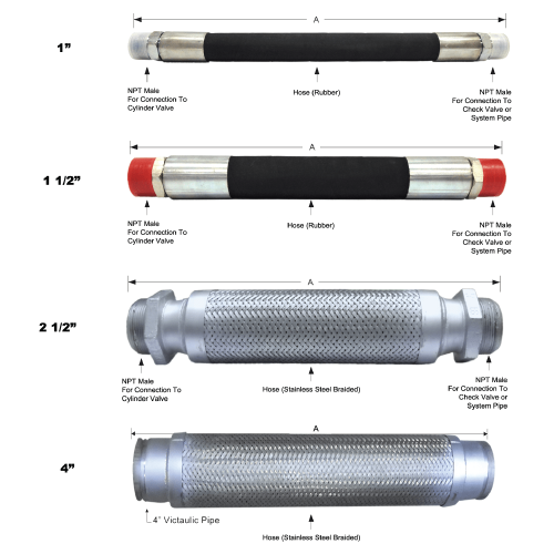
Flexible Hoses
[maxbutton id=”1″ url=”https://uniquefire.com/wp-content/uploads/2020/10/p53.pdf” ]


