Check Valve
[maxbutton id=”1″ url=”https://uniquefire.com/wp-content/uploads/2020/10/p54.pdf” ]
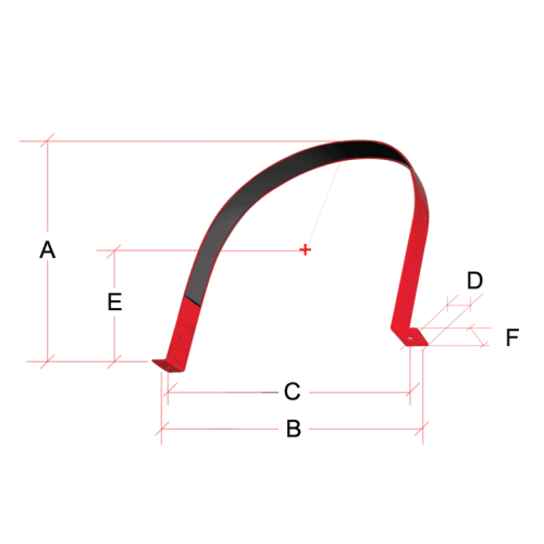
Cylinder Bracket
TECHNICAL DATA Part No. Description Cylinder O.D Mounting UFI 50139 20, 35 & 70 lb Cylinder Bracket 10.75” Wall UFI 60780 100 & 150 …
Discharge Nozzle
Discharge nozzles are made of aluminium with female pipe threads. These nozzles are available in two configurations, 180° sidewall and 360° central discharge patterns.
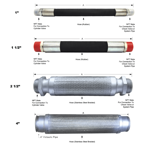
Flexible Hoses
[maxbutton id=”1″ url=”https://uniquefire.com/wp-content/uploads/2020/10/p53.pdf” ]
Latching Solenoid
Description
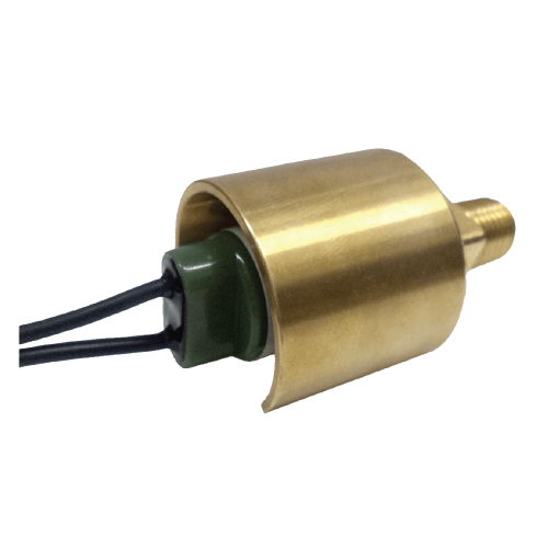
Latching Solenoid is utilized to open a Schrader valve on the top fitting connector of the cylinder valve. The application gives an answer to a quick reaction and a high latching power to be utilized with the UNIQUE Fire Extinguishing Liquid Agent. It was resolved that a latching solenoid with a discretionary nearby manual control head is the best answer for the application.
The actuator is held in the latching position without power until a flag from the operator discharge control board removes the permanent magnet. Whenever discharge, the latching solenoid opens the cylinder valve enabling the quenching medium to release from the cylinder into the system. The latching solenoid is designed with an emergency release local manual control to manually force the pin to depress the cylinder valve to release the extinguishing medium when needed. In order to reset the system, the solenoid is to be manually returned to the latched position. This custom latching solenoid designed specifically for fire protection systems is UL listed and tested in accordance with UL508.
Features
- High latching forces
- Fast response
- Options
- Manual release button cap
- Reset tool
- UL approval-recognized to UL864
- Tested in accordance with UL508
Specification
- Manual actuation force : 12-40lb ƒ (5.44 – 18kgƒ) max
- Operating force : 20.25 – 14.6lbƒ (90 – 65 N) min
- Power requirement : 24 VDC
- Current : 0.5A @ 24 VDC
- Electrical Connection : DIN 43 650-A / ISO 440 3 pin
- Operating Temperature Range : -4 to 131°F (-20 to 55°C)
- Weight : 1.9lbs (.86kg)
- Dimensions
- Body Diameter : 1.61 in (41 mm)
- Length : 4.17 or 5.9 in (106 or 150 mm) with manual actuation cap
Local Manual Control (Plunger Type)
The Local Manual Control Plunger Type features a local lever driven push rod that depresses a schrader check valve through the latching solenoid when fitted onto the top of the solenoid, thereby venting the pressure from the top of the piston in the cylinder valve, allowing the piston to slide upward and commence cylinder discharge.
- Use for manual actuation of cylinder
- Equipped with safety pull pin to prevent accidental discharge
- Solid brass construction
- Stainless steel operation lock-pin
PISTON ACTUATOR ASSEMBLY
Piston Actuator Assembly (P/N: UFI 61041)
- High quality brass construction
- Mounts directly on top of cylinder valves
- Self-venting
The Piston Actuator features a pneumatically driven piston that depresses a Schrader check valve, thereby venting the pressure from the top of the piston in the cylinder valve, allowing the piston to slide upward and commence cylinder discharge. The pneumatic pressure required to operate the Piston Actuator is obtained from the “M” port of a cylinder, which is designated as “Master” cylinder that is either mechanically and/or electrically actuated. Multiple cylinders equipped with Piston Actuators can be activated from one master cylinder using ¼” copper tubing or ¼” metal flex hose. The Piston Actuator mounts directly to a top plug adapter, which is located on top of the cylinder valve.
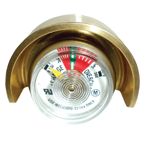
Pressure Gauge Guard
[et_pb_section fb_built=”1″ _builder_version=”3.22″ background_color=”rgba(255, 255, 255, 0)” custom_padding=”0px||||false|false” global_colors_info=”{}”][et_pb_row _builder_version=”3.25″ background_size=”initial” background_position=”top_left” background_repeat=”repeat” width=”100%” custom_padding=”0px||0px||false|false” global_colors_info=”{}”][et_pb_column type=”4_4″ _builder_version=”3.25″ custom_padding=”|||” global_colors_info=”{}” custom_padding__hover=”|||”][et_pb_wc_breadcrumb _builder_version=”3.0.47″ global_colors_info=”{}”][/et_pb_wc_breadcrumb][et_pb_wc_cart_notice _builder_version=”3.0.47″ …
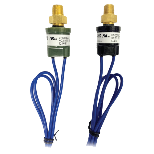
Pressure Supervisory Switch
TECHNICAL DATA Part No. Description Operation UFI 50138-1 360psi Normally Closed UFI 50138-2 360psi Normally Open
Pressure Supervisory Switch Guard
[et_pb_section fb_built=”1″ _builder_version=”3.22″ background_color=”rgba(255, 255, 255, 0)” custom_padding=”0px||||false|false” global_colors_info=”{}”][et_pb_row _builder_version=”3.25″ background_size=”initial” background_position=”top_left” background_repeat=”repeat” width=”100%” custom_padding=”0px||0px||false|false” global_colors_info=”{}”][et_pb_column type=”4_4″ _builder_version=”3.25″ custom_padding=”|||” global_colors_info=”{}” custom_padding__hover=”|||”][et_pb_wc_breadcrumb _builder_version=”3.0.47″ global_colors_info=”{}”][/et_pb_wc_breadcrumb][et_pb_wc_cart_notice _builder_version=”3.0.47″ …
Room Integrity Test
Enclosure Integrity Test
Now, the NFPA 2001, NFPA 12A, ISO 14520 and EN 15004 recognize an enclosure integrity test as part of the acceptance procedure for all clean agent systems. This includes halocarbon and inert agents. The comprehensive test and calculation procedure predicts how long the agent would stay in the room if it were ever discharged.
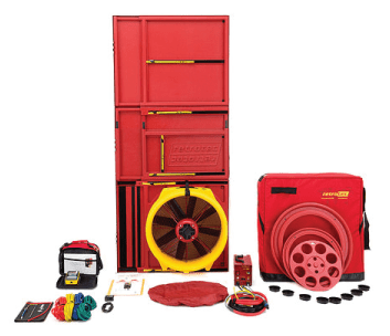
The Enclosure Integrity Test’s primary goal is to predict the enclosure’s retention time in the event that the Clean Agent Fire Suppression System is discharged. This is accomplished by performing a Door-Fan test.
What is a Door Fan Test?
Door Fan Test, also known as a Room Integrity Fan Test, is simply a way to measure the leakage of a protected room. A large fan is temporarily installed in the doorway of the protected room to be tested, with the fan blowing into the room (pressurizing the room). The fan speed is adjusted to obtain flow pressure equivalent to the pressure exerted during a fire suppression system discharge. The fan is then reversed on the door to draw air from the room (depressurizing the room). The airflow and pressure readings obtained are entered into a computer program designed to calculate the equivalent leakage area (ELA) for the room. Then, the software will calculate the retention time and determine whether it exceeds the minimum retention time of 10 minutes.
Shuttle Valve
TECHNICAL DATA Part No. Description UFI 50123 1” Shuttle Valve UFI 60619 1-1/2” Shuttle Valve


